External aerodynamics CFD analysis with adequate accuracy and short turnaround time.
Introduction :
In fluid mechanics terms, vehicles are bluff bodies travelling very close to the ground. Complex three-dimensional flow occurs around the vehicles with flow separation being very common. Such flow is typically analysed and optimized through external aerodynamics studies.External aerodynamics of sports cars, passenger cars and commercial vehicles which move at a relatively higher speeds, as such vehicles experience significant drag force which impacts performance and fuel consumption. Drag is mainly pressure drag; so, avoiding or reducing the separation is one of the main objectives of vehicle aerodynamics.
Here we are presenting a case study to depict how CFD analysis can be used to improve aerodynamics of a relatively slower speed commercial vehicle while overcoming above constraints.
Case Study:This case study is on a legacy design of auto rikshaw (3-wheeler). The body design is done in the last century and aerodynamic considerations were not the primary factors back then. If we want to convert such vehicle to electric vehicle, we need to consider aerodynamics and check how much electric power can be saved and also, if range can be increased through design improvements to the body shape.
Baseline design:
The shape of the 3-wheeler considered for this study is as shown below.
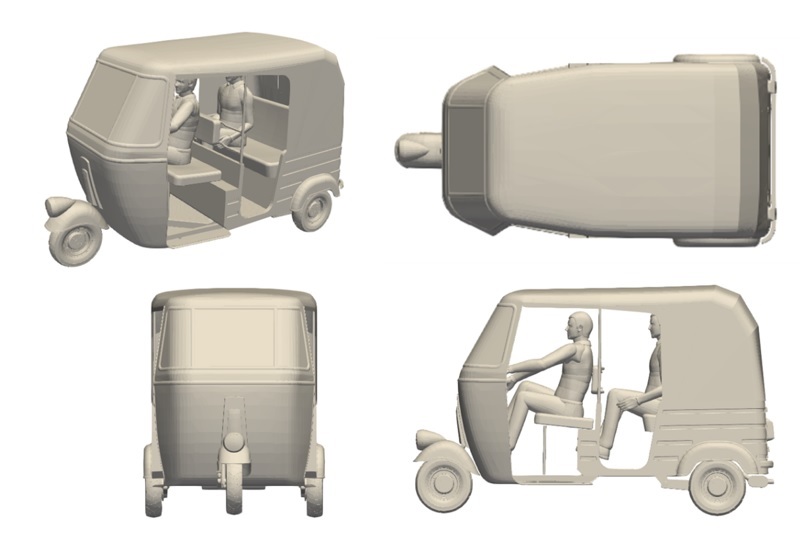
- This design is primarily used with gasoline engine.
- Engine power rating is around 7.5 kW@4500 RPM with peak torque 19 Nm@3200 RPM
- Carries maximum 4 persons, 1 driver + 3 passengers.
- Range of the vehicle is around 350km with full tank.
Revised design:
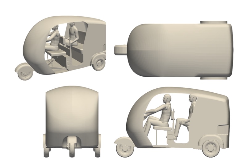
Based on the external aerodynamic study, the body shape is revised considering the constraints listed below.
- Change in overall envelope should be minimal. No change in the ground clearance.
- No change in the drive-train interfaces (track, wheelbase etc.)
- Driver and passenger comfort should not be affected. No interiors should be affected.
- No major changes in ergonomics etc.
The revised design is shown below. The features have scope for more optimization to further improve the aerodynamic performance.:
Boundary Conditions:
Both designs are analysed for aerodynamics performance at the vehicle speed of 15 m/s.
Results: Drag Coefficient (Ref. Wikipedia)

From the results, it can be observed that 17.4 % reduction in power requirement was achieved.
This will result in increase in the range of the vehicle as well.
Results:
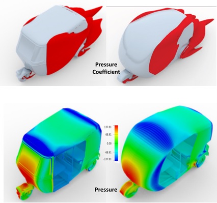
From the above plots for baseline design, design modifications to improve the drag coefficient were carried out with following considerations:
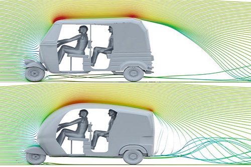
Results: Streamlines side view:
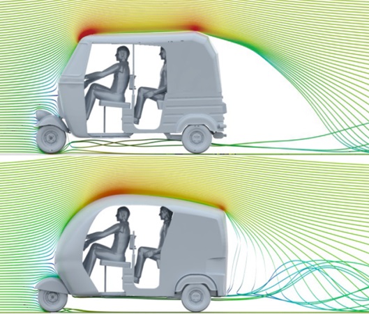
Results: Streamlines Top view:
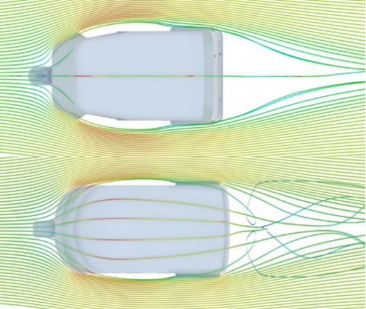
From these above streamlines plots, following improvements can be observed:
- Slight downward slope on the roof resulted into lot of improvement in the rear wake region.
- Air bleed feature helped to pass some air in the low pressure region.
Conclusions :
- Estimating the performance parameters related to external aerodynamics by CFD during vehicle development can yield significant benefits even for a relatively slower speed vehicle.
- Design improvements to the body shape based on external aerodynamics can help reduce drag, reduce power consumption and improve range. This is especially important for electric vehicles.

